

Introduction
Cable tray systems are essential for organizing, routing, and supporting electrical cables in industrial plants, commercial buildings, infrastructure projects, and power distribution networks. However, selecting the right cable tray involves more than choosing its width and material. Engineers must calculate the cable tray load capacity and determine the correct support spacing to ensure structural stability, operational safety, and long-term performance.
An incorrectly sized cable tray may experience excessive deflection, deformation, or support failure. Insufficient support spacing can also increase installation costs, while excessive spacing may compromise the tray's load-bearing performance. For EPC contractors, electrical consultants, and project engineers, understanding these calculations is important for reliable cable management system design.
In this guide, BNY Metalcoat explains how to calculate cable tray loading, select appropriate support spans, and identify the factors that influence tray performance.
In This Guide
What Is Cable Tray Load Capacity?
Cable tray load capacity refers to the maximum load a cable tray system can safely support under specified conditions. It depends on the tray's construction, material, dimensions, support span, and approved performance ratings.
The total load generally includes the weight of the installed cables and the self-weight of the tray. Additional loads, such as accessories, environmental effects, or maintenance-related loads, must be considered wherever applicable to the project design.
Cable tray capacity is commonly expressed as kilograms per metre (kg/m) or kilonewtons per metre (kN/m). The manufacturer's declared safe working load (SWL) or uniformly distributed load (UDL) should be checked against the actual installation requirements.
Different tray designs offer different structural characteristics:
- Perforated cable trays: Suitable for many power and control cable installations where ventilation and cable support are required. See perforated cable trays.
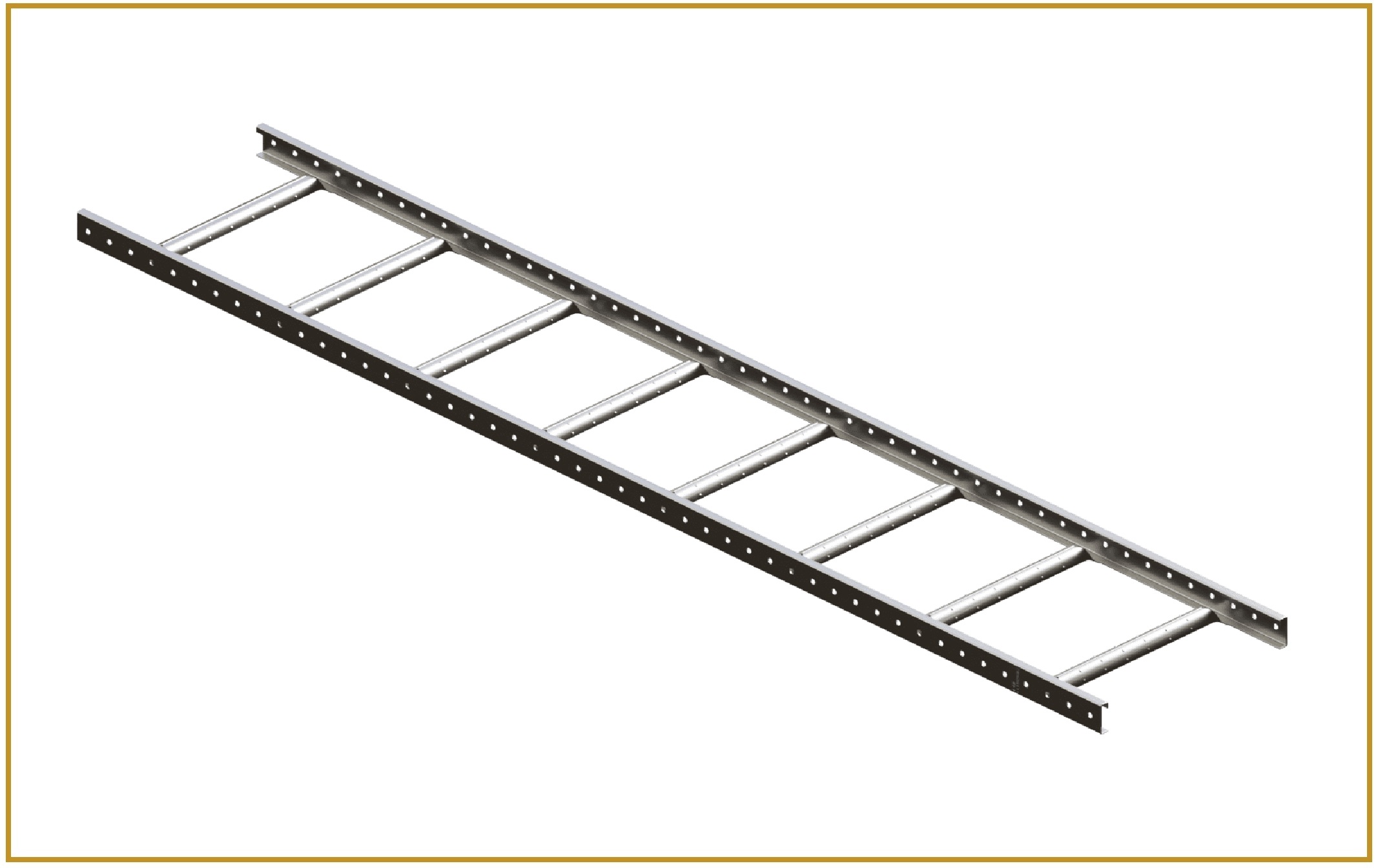
- Ladder cable trays: Commonly selected for heavier cable installations and applications requiring open construction. See ladder type cable trays.
- Wire mesh cable trays: Often used for lightweight cabling, communication systems, and data infrastructure. See wire mesh cable trays.
- GI and hot-dip galvanized cable trays: Selected where the required corrosion protection and environmental conditions justify the specified finish. See GI and hot-dip galvanized cable trays.
The tray type alone does not establish its capacity. The exact dimensions, sheet thickness, construction, support configuration, and manufacturer-rated performance must all be considered.
Factors That Affect Cable Tray Load Capacity
Before performing calculations, engineers should identify the factors that influence the tray's load-bearing performance.
1. Tray Width and Side Height
Tray width determines the available cable installation area, while side height and profile influence structural behaviour. A wider tray is not automatically stronger, as its performance also depends on material thickness, reinforcement, and design.
2. Material and Thickness
Cable trays may be manufactured from mild steel, galvanized steel, stainless steel, or other specified materials. Material properties and sheet thickness influence stiffness, strength, and resistance to corrosion.
For example, BNY Metalcoat offers perforated cable trays in different thickness options for light, medium, and heavy-duty applications. The appropriate configuration should be selected according to the project's required loading and environmental conditions.
3. Support Span
Support span is the distance between adjacent tray supports. As the span increases, the tray generally experiences greater bending and deflection under the same uniformly distributed load.
Consequently, a tray's rated load must always be evaluated at the corresponding support span.
4. Cable Weight and Arrangement
The number, size, and weight of installed cables directly affect the total loading. Cable distribution also matters because a concentrated load may produce different stresses from a uniformly distributed load.
5. Joints, Fittings, and Installation Conditions
Splices, bends, tees, reducers, vertical sections, and cantilever supports can influence load distribution. Temperature, vibration, corrosion exposure, and the strength of the supporting structure may also affect the installation's overall reliability.
How to Calculate Cable Tray Load Capacity
A practical calculation starts with the cable schedule and the manufacturer's load data.
Step 1: Calculate the Total Cable Weight per Metre
Determine the weight per metre of every cable type installed in the tray. Multiply the weight of each cable by the quantity installed.
Formula:
For example, consider a tray containing:
- Four power cables, each weighing 2.5 kg/m.
- Six control cables, each weighing 0.4 kg/m.
The total cable load per metre is:
Control cable load = 6 × 0.4 = 2.4 kg/m
Total cable load = 10 + 2.4 = 12.4 kg/m
These figures are illustrative. For an actual project, use the cable manufacturer's documented weights and the approved cable schedule.
Step 2: Include the Tray's Self-Weight
The tray itself contributes to the total structural load.
Assume the selected tray weighs 4 kg/m. The combined service load is:
Total service load = 12.4 + 4 = 16.4 kg/m
Additional loads should be included when required by the applicable design criteria and the manufacturer's rating method. Do not add loads twice if the published rating or calculation basis already accounts for them.
Step 3: Account for Future Cable Expansion
Electrical installations may require spare capacity for future cables. The design team should establish a suitable allowance based on the project specification and expected expansion.
For illustration, assume a 20% allowance on the calculated cable load:
Revised design load = 12.4 + 2.48 + 4
Revised design load = 18.88 kg/m
This is a preliminary service-load calculation, not a certified tray rating. The allowance must be selected for the actual project rather than applied universally.
Step 4: Compare the Design Load with the Manufacturer's Rating
Check the manufacturer's load table for the exact tray model, width, material thickness, and support span.
The declared allowable load must be suitable for the calculated loading under the applicable rating method. Also verify the specified deflection limits and any restrictions concerning joints, fittings, or concentrated loads.
Do not assume that a tray can support a particular load merely because its dimensions resemble those of a different model.
How to Calculate Cable Tray Support Spacing
Cable tray support spacing is the distance between adjacent support points along the tray route. It directly affects bending behaviour, deflection, and the load carried by the tray system.
Step 1: Identify the Rated Support Span
Start with the manufacturer's approved load-versus-span table. Identify the maximum permitted span for the selected tray and required design load.
For example, if the manufacturer confirms that a particular tray configuration can support the required load at a 1.5 m span, that span may be considered for the design, subject to all other installation requirements.
This does not mean 1.5 m is suitable for every tray. Support spacing must be established using the actual product's performance data.
Step 2: Calculate the Number of Support Intervals
For a straight, uniformly supported run, the preliminary number of intervals can be estimated using:
Suppose a straight tray run is 18 m long and the selected support spacing is 1.5 m.
Therefore, the run contains 12 support intervals. If supports are installed at both ends of this uninterrupted run, 13 support points are required.
This is a simplified layout calculation. Actual support locations must account for end conditions, joints, bends, tees, risers, and project-specific installation requirements.
Step 3: Check the Load on the Supports
For a preliminary estimate of an interior support's tributary load under a uniformly distributed load, use:
Using the revised design load of 18.88 kg/m and a 1.5 m spacing:
Support load ≈ 28.32 kg
This is an approximate vertical load contribution from the tray and its contents over the support's tributary length. It is not a complete support design. Actual reactions depend on span continuity, support arrangement, joint locations, and load distribution. Brackets, anchors, threaded rods, and the building structure must be checked separately.
Step 4: Verify Deflection and Structural Strength
The tray must satisfy the applicable strength and deflection criteria at the selected span. A tray may carry the calculated weight yet still deflect excessively.
Use the manufacturer's tested or engineered load tables rather than relying only on a simplified beam formula. The final arrangement should also comply with the applicable project standards and installation specifications.
Standards and Best Practices for Cable Tray Design
IEC 61537 addresses requirements and testing for cable tray and cable ladder systems, including mechanical performance and safe working load assessment. Engineers should verify the applicable edition and the requirements referenced in their project specifications.
For reliable cable tray installation:
- Select the tray based on documented loading requirements, not appearance alone.
- Verify the manufacturer's load rating at the actual support span.
- Position supports in accordance with approved installation drawings and product instructions.
- Check joints, fittings, cantilever arms, anchors, and supporting structures.
- Consider corrosion protection and the operating environment.
- Reassess the design when cable quantities, cable weights, or routing conditions change.
For additional technical information, consult BNY Metalcoat's perforated cable trays, powder-coated cable trays, and cable tray manufacturing solutions.
Common Mistakes to Avoid
Incorrect assumptions during cable tray selection can lead to unnecessary costs or unsafe installations. Avoid these common mistakes:
- Using a generic load value: Capacity varies with tray construction, thickness, width, and span.
- Ignoring tray self-weight: The supporting system must account for the applicable dead load.
- Selecting support spacing without checking load tables: A familiar spacing is not automatically suitable for every tray.
- Overlooking cable growth: Future additions can exceed the original design allowance.
- Ignoring support hardware: A strong tray cannot compensate for undersized brackets, anchors, or structural members.
- Assuming fittings behave like straight sections: Bends, tees, and risers may require specific support arrangements.
- Confusing service load with safe working load: Compare values only when their definitions, units, and rating methods are compatible.
Conclusion
Calculating cable tray load capacity and support spacing requires a systematic assessment of cable weight, tray self-weight, future expansion, product construction, and manufacturer-rated performance. Engineers should first calculate the expected distributed load, then select a tray and support span that satisfy the applicable strength and deflection requirements.
For EPC firms, consultants, and electrical contractors, accurate load calculations help improve installation reliability, simplify design reviews, and reduce the risk of costly modifications. BNY Metalcoat provides cable management solutions, including perforated, ladder-type, galvanized, and powder-coated cable trays, to support varied industrial and infrastructure applications.
Frequently Asked Questions
Cable tray load capacity is the load a specified tray configuration can safely support under defined conditions. It depends on the tray design, dimensions, material thickness, support span, and declared performance rating.
Multiply each cable's weight per metre by the number of cables installed, then add the applicable tray self-weight and other required loads. Include a project-approved allowance for future cables when necessary.
There is no single support spacing suitable for all cable trays. The appropriate span depends on the manufacturer's load tables, tray construction, cable loading, fittings, and installation requirements.
Increasing the distance between supports generally increases bending and deflection under the same distributed load. The allowable load must therefore be checked against the manufacturer's rating for the proposed span.
Ladder-type and appropriately engineered heavy-duty perforated trays may be suitable for heavy cable installations. The final choice should be based on cable weight, environment, tray dimensions, support span, and verified product ratings.
Yes. Tray self-weight contributes to the structural load. Engineers should include it according to the applicable design method and ensure that loads already covered by a published rating are not counted twice.
IEC 61537 covers cable tray and cable ladder systems, including mechanical requirements and safe working load testing. The applicable edition and any additional national or project-specific requirements should be verified before design approval.
Start with the cable schedule, cable weights, required tray width, environmental conditions, and expected future expansion. Compare the resulting design load with manufacturer data for the exact tray configuration and support span, and obtain engineering approval for the complete support system.
Share your cable schedule and span for a project-specific recommendation
Call +91 7020753022 / +91 9067686956 or email bnymetalcoat@gmail.com
Request a Cable Tray Quote