

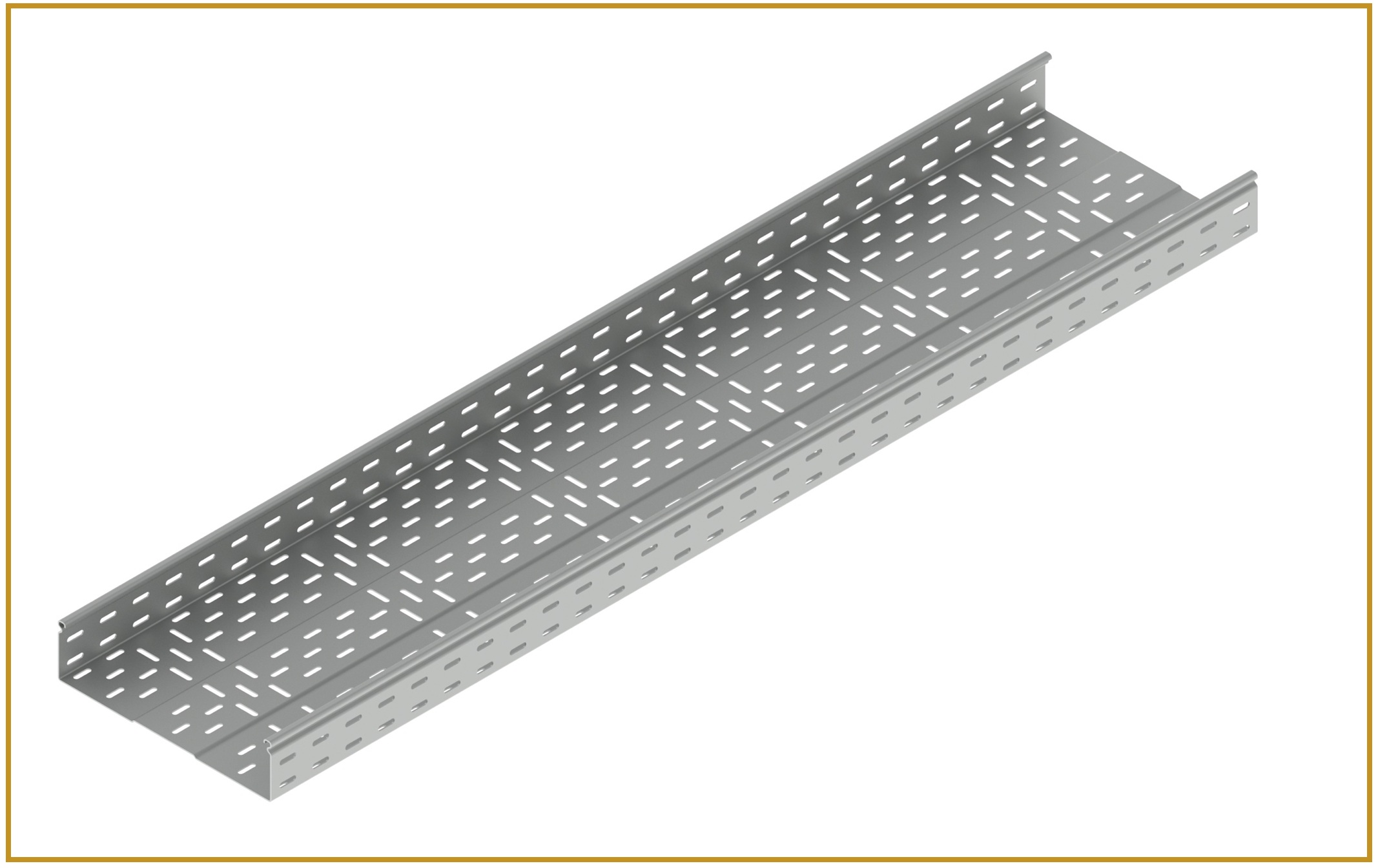
Choosing the correct cable tray size is an essential part of designing a safe, organized, and efficient electrical installation. Whether you are planning an industrial facility, commercial building, data centre, or infrastructure project, the right cable tray helps support electrical cables, simplifies maintenance, and allows for future expansion. An incorrectly sized tray, on the other hand, can lead to overcrowding, installation difficulties, inadequate load support, and unnecessary project expenses.
Effective cable tray size selection involves more than measuring the available installation space. Engineers and contractors must consider cable quantity, cable diameter, weight, installation conditions, ventilation requirements, support spacing, and applicable electrical standards.
This guide explains how to choose the appropriate cable tray width and depth, calculate cable capacity, and select a suitable tray for your project.
In This Guide
1. Understand the Basics of Cable Tray Dimensions
Before selecting a cable tray, it is important to understand its primary dimensions and their functions.
- Width: The horizontal distance across the tray, which determines how many cables can fit side by side.
- Depth: The height of the tray sidewalls, which influences the available cable space and permitted cable arrangement.
- Length: The length of an individual tray section used to create the complete cable routing system.
Cable tray dimensions are generally specified in millimetres. Common options include widths of 100 mm, 150 mm, 200 mm, 300 mm, 450 mm, and 600 mm, with side depths ranging from approximately 50 mm to 150 mm. Actual dimensions vary by tray type and manufacturer.
Understanding these measurements helps engineers prepare accurate specifications and avoid compatibility issues during installation.
2. Calculate the Number and Size of Cables
The first step in cable tray size selection is preparing a cable schedule. This document should identify the number of cables, their outside diameters, their types, and their intended routes.
For example, a project may include power cables, control cables, instrumentation cables, and communication cables. Each category can have different space, separation, and installation requirements.
For cables arranged in a single layer, estimate the required width by adding their outside diameters and the necessary spacing between them.
Basic formula:
Suppose six cables each have an outside diameter of 20 mm. Their combined width is 120 mm before adding any spacing or design allowance. The final tray width must accommodate the complete arrangement while meeting the project's cable separation and fill requirements.
For multiple cable sizes, calculate the combined dimensions rather than assuming every cable occupies the same space. Also account for bends, terminations, and any restrictions specified by the cable manufacturer or applicable standards.
3. How to Choose the Right Cable Tray Width
Cable tray width determines the usable horizontal space available for cable routing. Selecting a width that is too small may result in overcrowding, difficult cable installation, and limited room for future additions.
Consider the following factors when choosing a suitable width:
Cable quantity and diameter
Calculate the space occupied by the cables using their actual outside diameters. Larger power cables may require substantially more space than small control or communication cables.
Cable arrangement
Determine whether the cables will be installed in a single layer, in permitted multiple layers, or in separate groups. The arrangement must follow the relevant installation standards and cable manufacturer's recommendations.
Future expansion
Industrial and commercial installations often require additional cables as equipment or systems expand. Allowing suitable spare capacity during the design stage can reduce the need to replace or extend the tray system later.
Electrical separation
Power, control, instrumentation, and data cables may require separation to reduce interference or comply with project specifications. This can affect the usable tray width and may require separate trays or dividers.
Available installation space
Check the width of ceiling voids, cable corridors, equipment rooms, and support structures before finalising the tray dimensions. The selected width must fit the route without obstructing other building services.
A wider tray is not automatically the best option. The goal is to provide sufficient usable space while maintaining structural performance, accessibility, and cost efficiency.
4. How to Select the Correct Cable Tray Depth
Cable tray depth refers to the height of its sidewalls. It influences the available vertical space for cables and must be selected according to cable arrangement, tray construction, and loading requirements.
The following considerations help determine the appropriate depth.
Cable diameter and layering
For single-layer installations, the cable arrangement may fit within a relatively shallow tray. Where multiple layers are permitted, greater depth may be required. However, increasing tray depth does not automatically make every cable arrangement acceptable.
Cable weight and tray strength
Tray depth is only one factor affecting structural performance. Material thickness, tray design, support spacing, span, joint construction, and total cable load must also be evaluated. A deeper tray should not be assumed to carry a greater load without checking the manufacturer's load data.
Accessibility and maintenance
Choose a depth that supports practical cable installation and inspection. Excessively deep trays can make cable identification and maintenance more difficult in some installations, particularly where access is restricted.
Ventilation and heat dissipation
Cable grouping and tray construction can affect heat dissipation. Perforated and ladder-type trays provide different ventilation characteristics from solid-bottom systems. The selected arrangement must comply with cable ampacity requirements and applicable installation rules.
The correct depth is therefore a balance between usable cable space, structural requirements, accessibility, and thermal performance.
5. Consider Cable Tray Fill Capacity
Cable tray fill capacity describes how much of the available tray space is occupied by cables. Appropriate fill is important for installation, inspection, heat management, and future maintenance.
There is no single fill percentage that applies to every cable tray installation. Permitted fill depends on cable type, tray construction, installation method, governing standards, and project specifications.
For a single-layer arrangement, compare the total cable widths with the usable tray width. For permitted multilayer arrangements, calculate the cable area or apply the specific fill method required by the governing standard.
Illustrative example: If the combined cable widths total 180 mm and the usable tray width is 300 mm, the simple width occupancy is:
Do not use the same fill calculation for every installation. Confirm the applicable requirements under the relevant electrical code and project specification.
6. Select the Right Cable Tray Type
Cable tray type also affects the sizing decision. The most suitable option depends on cable weight, ventilation, environmental exposure, and accessibility.
- Perforated cable trays: Suitable for many commercial and industrial cable-routing applications where cable support, ventilation, and practical maintenance access are important.
- Ladder-type cable trays: Often used for heavier power cables and installations that require a robust support arrangement and good ventilation.
- Wire mesh cable trays: Commonly used for data, communication, and fibre-optic cabling, particularly where flexibility and accessibility are useful.
- Raceways and trunking: Provide a more enclosed routing option where cable protection and a neat installation are priorities.
Review the available perforated cable trays, ladder-type cable trays, wire mesh cable trays and raceways and trunking to understand the options for different project requirements.
7. Check Cable Weight and Support Spacing
Correct dimensions alone do not guarantee a safe installation. The tray must be capable of supporting the combined cable weight over the specified support span.
Calculate the expected cable load per metre using the cable schedule and manufacturer's weight data. Then compare this load with the selected tray's published load rating for the intended support spacing.
Consider additional loads where relevant, including covers, accessories, environmental conditions, and maintenance-related requirements specified by the design.
Support spacing must follow the tray manufacturer's recommendations and the applicable engineering requirements. Check joint locations, bends, tees, reducers, and vertical sections carefully, as these areas may need additional support.
Always verify load-deflection data for the actual tray configuration rather than selecting a tray based only on width or depth.
8. Choose the Right Material and Surface Finish
Environmental conditions are another important factor in cable tray sizing and specification.
- Galvanised steel: A common option for general industrial and commercial installations, with corrosion protection depending on the galvanising process. See GI cable trays.
- Hot-dip galvanised steel: Often considered for outdoor or more demanding environments where suitable zinc protection is required. See hot-dip galvanized cable trays.
- Stainless steel: Useful in applications that require particular corrosion resistance, subject to the grade and exposure conditions. See stainless steel cable trays.
- Powder-coated steel: Provides a finished surface and an additional protective coating suitable for selected indoor and industrial environments.
Assess humidity, chemical exposure, outdoor weather, temperature, and maintenance requirements before deciding on the material and finish. Material selection should be coordinated with the required tray strength, thickness, and support design.
9. Common Cable Tray Sizing Mistakes to Avoid
Avoid these frequent design and installation errors:
- Selecting tray dimensions without preparing a complete cable schedule.
- Ignoring cable outside diameters and required separation.
- Choosing tray depth based only on visual appearance.
- Overlooking future cable additions and maintenance access.
- Assuming a tray's load capacity from its dimensions alone.
- Failing to verify support spacing, joint positions, and fitting compatibility.
- Using the same fill assumptions for different cable types and installation methods.
- Ignoring environmental exposure when specifying tray material and finish.
A coordinated review by the electrical designer, contractor, and cable tray supplier helps prevent costly changes during installation.
10. Final Checklist for Cable Tray Size Selection
Before placing an order, confirm the following:
- The cable schedule includes all current cables and anticipated additions.
- Cable outside diameters and permitted arrangements have been checked.
- Tray width and depth meet the required space and fill criteria.
- Cable weight and support spacing comply with the manufacturer's load data.
- The tray material and finish suit the installation environment.
- Bends, tees, reducers, covers, couplers, and supports are compatible.
- The design follows applicable electrical standards and project specifications.
Conclusion
Choosing the right cable tray size, width, and depth requires a systematic assessment of cable quantity, dimensions, arrangement, weight, environmental conditions, and future requirements. A properly sized system improves cable organisation, simplifies maintenance, and supports reliable electrical infrastructure.
For successful cable tray size selection, engineers and contractors should combine accurate calculations with verified load ratings, appropriate material specifications, and compliance with applicable standards.
BNY Metalcoat provides cable management solutions including perforated, ladder-type, wire mesh, galvanised, and powder-coated cable trays, along with compatible accessories. Explore the available products at BNY Metalcoat to identify options suited to your project's cable routing and support requirements, or contact our team with your cable schedule.
Frequently Asked Questions
Choose a cable tray based on cable quantity, outside diameter, arrangement, fill requirements, total weight, and future expansion needs.
Add the outside diameters of the cables arranged side by side, then account for required spacing, separation, and applicable installation standards.
The appropriate depth depends on cable diameter, permitted cable layering, tray design, accessibility, and load requirements.
There is no universal fill limit for every installation. The allowable capacity depends on cable type, tray configuration, applicable electrical standards, and project specifications.
Yes, but size alone does not determine capacity. Material thickness, tray construction, support spacing, and cable weight also influence load-bearing performance.
Ladder-type and perforated cable trays are common industrial choices. The best option depends on cable weight, ventilation, environmental conditions, and installation requirements.
Yes. Allowing suitable spare capacity during the design stage can accommodate future cables and reduce costly modifications.
Verify tray dimensions, cable fill, load ratings, support spacing, material finish, accessory compatibility, and compliance with applicable standards.
Share your cable schedule for a project-specific tray recommendation
Call +91 7020753022 / +91 9067686956 or email bnymetalcoat@gmail.com
Request a Cable Tray Quote